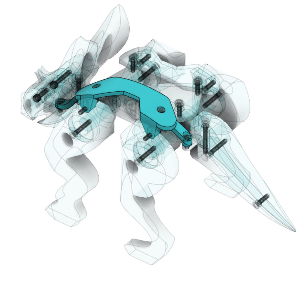
The instructions are based on a case study of how the Tectonic Utahceratops was developed - from conception, through production. Although the subject is a mechanical dinosaur toy, the process would be the same for any type of multi-component product.
The instructions include the following topics:
Step 1: Start with a sketch
It doesn't have to be pretty, or drawn with a ruler. It only needs to convey an idea. The first sketch I make for my dinosaur toys is generally a sketch of the skeleton. I call this "sketch 0" because the skeleton doesn't illustrate the design concept for the toy. It is only a template that can be used to overlay other ideas or design iterations.

Image above: Sketch 0, Skeletal background.
After creating sketch 0, I study different concepts for how the toy will look, and work:

Image above: Interconnection motion study. This sketch determined the type of motion that I wanted to incorporate into the design. It features the overview and some detailed considerations, but is not the final design.

Image above: Study for shifting shoulder plate appearance


Image above: Final concept design for fully-articulating Tectonic Utahceratops. The sketch illustrates individual components and the way the product will be assembled.
Step 2: Enter 3D modeling software
After creating the background and concept sketches, scan them as .jpgs. The next step is bring a sketch into 3d modeling software and create a digital 3D model of the design.
The 3D modeling software I use is Autodesk Fusion 360. There are many other software choices - each software with various pros and cons. Fusion 360 has some quirks, but works well for me especially because of my backround with Autodesk AutoCad and Revit.
After opening the software, create a new file and set the project units. I typically work imperial units. However, after completing my 3d model I change the settings to metric because that's what my 3D printer utilizes (we'll get there later).

Image above: Setting the model units
Next, familiarize yourself with the 3D environment. Note that there is an origin toggle, and a graphic representation (towards the upper right) indicating the vantage point from which you are viewing the 3D environment. Below the graphic representation, there is a small pull down icon that can be used to toggle between isometric view and perspective view.

Image above: Identifying the model origin
The cube shaped orientation icon can be used to change the view. Click on any of the faces, or corners to re-orient the view. Alternatively, you can use your mouse to pan or orbit around the environment. Holding down your center mouse button allows you to pan. Holding down the center button while holding shift allows you to orbit. There is a toggle switch at the bottom center of the screen that determines whether you have a constrained, or free orbit. Try both to see which one feels better for you:

Image above: Clicking a face of the 3d origin icon to view the model from the right side
Step 3: Prepare to Import the design sketch into the 3D modeling software
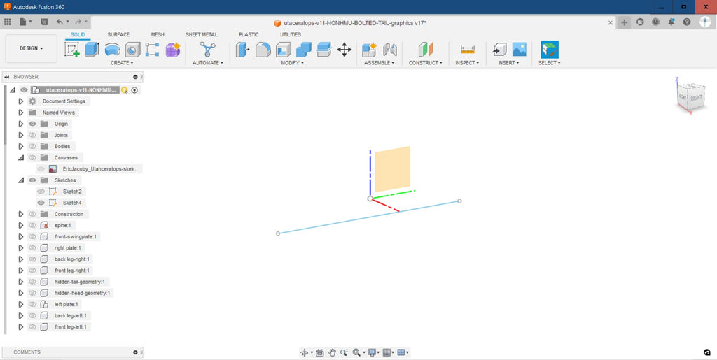
The empty 3D environment is infinite and without scale, so before importing a design sketch, create a reference line with a known dimension. To do this, launch the Create Sketch command from the Create tab. Select a surface for your sketch and draw a line that represents the actual or approximate length of one of your product sides. Keep in mind that the length of your part needs to be able to fit within the build volume of your 3D printer.

Image above: Launching the sketch command.

Image above: Selecting a plane for the sketch

Image above: Drawing a line during a sketch command

Image above: Drawing a reference line to define scale of environment

Image above: Closing the sketch command and viewing the reference line in the 3D environment
Step 4: Import the design sketch into the 3D modeling software
Now that you are familiar with the 3D environment and have a reference line for scale, use the Insert Canvas command from the Insert Tab:

Image above: Launching the insert canvas command.

Image above: Selecting the source location for the image file.

Image above: Selecting the surface on which the canvas will be placed

Image above: Adjusting the position and scale of the canvas in relationship to the reference line

Image above: Inspecting the canvas and reference plane
Step 5: Organize modeled components in the 3D software
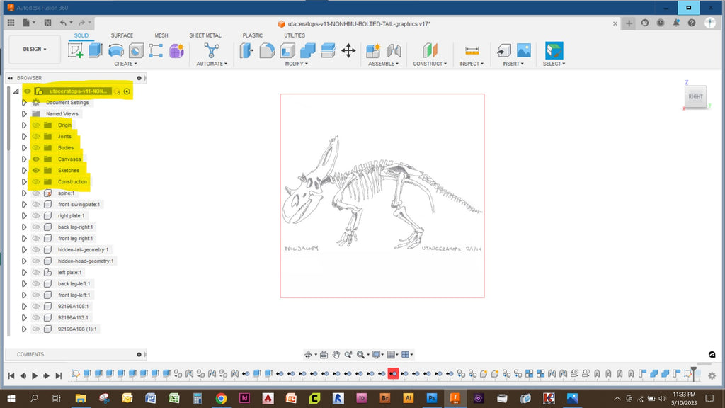
Before modeling any parts it is important to understand how modeled parts will be organized within the software. The project browser has a principal name at the top. It has the following subcategories: Origin, Joints, Bodies, Canvases, Sketches, and Construction. We used the Sketch subcatagory when we inserted the reference line.

Image above: The principal model has subcategories
If you plan to model multiple parts that fit together, the recommendation is to create a Component for each part. Use the Create Component command from the Create Tab. Once you create a new component you can give it a unique name:

Image above: Components can be added as subcategories to the Principal Model.
Each Component has the same subcategories as the Principal Model: Origin, Joints, Bodies, Canvases, Sketches, and Construction. These additional subcategories allow you to isolate individual components, sketches etc. from one another:

Image above: Each component also has subcategories.
Step 6: Modeling the first part
Note that when Sketch 0 was inserted in the Principal Model, it populated into the sketch folder. This was deliberately done so that sketch 0 can remain visible while separate components are created.
To create the first modeled part, activate (or create) the desired component, use the sketch command, select the surface of the origin which is coplanar with sketch 0, then use the line, circle, or arc command to define the outline for your first part. Note how Sketch 0 is a reference for the sketched shape.

Image above: Activating the component, and drawing a sketch within the component
Once the sketch is completed, click the Close Sketch button at the top right. Now use the Extrude Command from the Create Tab, or right click on your sketch surface. Selected, drag the extruded volume to the desired depth, or input the desired extrude length adjacent to the extrusion arrow, or within the Extrude Command pop-up menu:

Image above: Launching the Extrude Command and extruding the sketch into a volume.
Note that after making an extrusion, the solid volume results as a Body and populates within the Bodies Folder. The Body can be toggled on and off with the eye icon. Also note that the sketch is automatically hidden after a Body is created. The sketch can be revealed with the eye icon.
It is recommended to extrude half of the overall component thickness on one side of the origin, and the other half of the component thickness on the other side of the origin. The example above illustrates a .125" extrusion to the right of the origin, and the image below illustrates a.125" extrusion on the left of the origin. This approach keeps Sketch 0 in the middle of the model. and the modeled component centered around the origin:

Image above: Extruding symmetrically across y axis
Other methods for creating form from sketches include the Revolve Command, Sweep Command, or Loft Command.
The part modeled in this demonstration is longer than required for the final product. To remove the unwanted portion of the solid, the Extrude Command can be used to subtract form. Extruding a sketch through a visible body results in subtraction.
The example below illustrates the use of an Offset Plane as a plane for a sketch to be used for subtraction.

Image above: Creating an offset plane with a dimension from another surface.

Image above: Selecting offset plane for sketch surface

Image above: Drawing sketch for subtraction

Image above: Extruding sketch through model to subtract

Image above: Resulting component shape after subtraction.
Step 7: Modeling additional parts
After you have modeled a part, more parts can be modeled with the same techniques:

Image above: Utilizing sketches, additive/subtractive extrusions to model additional components
Sketches can be drawn in any orientation, or on any plane that you create. Additionally, parts can be modeled with multiple extrusions, subtractions, or rotations to create parts with increasing complexity:

Image above: Utilizing sketches in multiple orientations

Image above: Additive/subtractive extrusions can occur from multiple origins to develop parts with increasing complexity.

Image above: Keeping individual components, bodies, and sketches organized is crucial.
Step 8: Importing your 3d model for slicing
The illustrations above are "solid" 3d models. 3D printers do not understand solid models. Instead 3d printers require instructions for how convert plastic filament into a physical object (i.e. move the extruder along any of 3 axis, change the temperature of the print bed, or hot-end, and extrude / retract filament). The instructions for 3D printers are packaged as .gcode files.
To turn your design into a .gcode file you need to use "slicing" software. Slicing software doesn't read solid 3d models either. Slicing software utilizes "shell" models. To get a shell model, you must export it from your 3d modeling software. I generally export shell files from Fusion as .STL files.
To save your part as a a shell, select a group of components, or bodies from the navigation bar, right-click and select "Save as Mesh". Then refer to the "Save as Mesh" menu to select the units, file type and quality. Note that I selected .STL, metric and high refinement. Once executed, I select a location for the .STL file on my computer.

Image above: Selecting the component and saving it as a mesh

Image above: Adjusting the mesh settings prior to export

Image above: Organizing the .STL files in an easily accessible folder
Step 9. Preparing your your model for Slicing
After the required shell files have been created, they need to be processed by a slicing software to create the .gcode instructions for the 3D printer. There are many slicing softwares. The two slicing softwares I utilize correspond to the two 3D printers I use. Either software can be configured to different printers. For this guide, I am using Prusa Slicing Software.
Open the slicing software and adjust the settings to the correct make/model of 3D printer that you will be using. The 3D printer I am using is the Prusa i3 MK3

Image above: the Platter and empty digital print volume of Prusa Slicing software
Use the Import menu to select the .STL shell file that you intend to Import:

Image above: Selecting a file to import into the slicing software
Once your part is loaded on the platter, adjust the settings to the type/thickness of filament, as well as the desired print quality. This demonstration illustrates 1.75mm PLA filament . Follow the 3D printer's manufacturer's instructions for the recommended size and type of PLA, as well as how to load the filament:

Image above: Changing the basic filament settings for your print
Step 10: Determining Support Conditions
3D printing works with the continuous extrusion of a fine thread of melted plastic filament. Individual layers are laid down one at a time on the platter. The layers gradually build up to create a three-dimensional volume. This works well for shapes like cylinders, or cubes that have outside surfaces which are perpendicular to the platter, but consider for a moment that each filament layer is like a layer of bricks. Bricks stack perfectly when stacked vertically. And bricks stack well with a corbelled overhang. However a brick cannot stack above a brick below with more than about half a brick's length of overhang. This is the same for printer filament. Small, gradual overhangs in the shape can be printed, but large abrupt, extended overhangs cannot be printed unless they have "support" below them.
In the event that your part has overhanging elements, you will need to utilize the Support features of the slicing software. Find the Support settings in the Print Menu. For the Prusa Slicer, the controls can be automatic, or dialed in with more specifics. The example below uses automatic supports with a 50% overhang threshold (meaning that an overhang with less than a 45% angle will not receive supports):

Image above: Selecting automatic Supports
Supports can also be selected from Build Plate only, or with Support Enforcers. Build Plate only is support for any qualifying overhand directly above the build plate:

Image above: Selecting Supports from the Build Plate Only
Selecting the Support Enforcers is a way to restrict the supports only to where you desire them. Enforcers can be Painted on with the Paint On Supports command:

Image above: Selecting the Paint On Supports command
The Supports can be painted with a variety of paintbrush, or eraser settings:

Image above: Painted location for Supports
Step 11: Slicing your model and preparing the G Code
Once you've made your support settings, the model can be sliced. Press the Slice Now button at the bottom right, or the sliced cube graphic at the bottom left:

Image above: Slicing the model
The slicer software will now generate an image of the sliced model layers, the extruder path, the supports, the output time, and the quantity of filament required:

Image above: The sliced model and print data
The example part above can be printed with the support, however there is an inefficiency to the amount of support used. Unnecessary supports waste filament, cause longer print times, and are difficult to remove. For the next example, I chose to re-arrange the position of the part on the platter to reduce the amount of support required.
To re-arrange the model you can use the Move and or Rotate command, or select the Place on Face Command and select the desired face to be aligned to the platter:

Image above: Launching the Place on Face command

Image above: Selecting the face to be placed on the platter

Image above: The part now re-aligned with the platter

Image above: The resulting supports required with the new part arrangement
Next, arrange all of the product parts on the platter and adjust for the most efficient supports:

Image above: Final arrangement of parts to be sliced and printed
Once your parts are arrange, run the Slice Command. Your parts are now ready to be exported to .gcode. Push the Export G Code button and select the location to save your .gcode file on your computer.

Image above: Exporting the .gcode file from the slicer program

Image above: Saving the .gcode file to the computer.
Step 12: 3D printing your part
Save the G Code file onto an SD card and insert the SD card into the SD reader on the 3D printer. Power on the 3D printer and make sure that the filament is loaded correctly. Find the command on the printer interface to Print from SD. Select Print from SD. Enjoy watching your design become physical reality.
(Step 12 assumes that you are familiar with the operation of your 3D Printer. If not, find a tutorial or instruction manual for operating your specific 3D Printer)

Image above: The 3D Printer printing parts